Interpreting a Telehandler’s Load Charts
by Josh Taylor - Product Manager On Mar 1, 2018, 03:00 AM
Subscribe To Aerial Pros
Filter by tags
When the job calls for lifting, moving and placing materials on jobsites, telehandlers are a great go-to equipment choice, because these machines can complete all those tasks with just one unit — as opposed to needing a combination of machines, such as a skid steer loader, forklift, and small crane to complete a job.
Telehandlers offer operators loading and unloading capabilities, as well as the ability to move and place heavy loads like steel, masonry and bricks. Because of these machines’ ability to do so many jobs, they have become a staple on construction and landscaping projects.
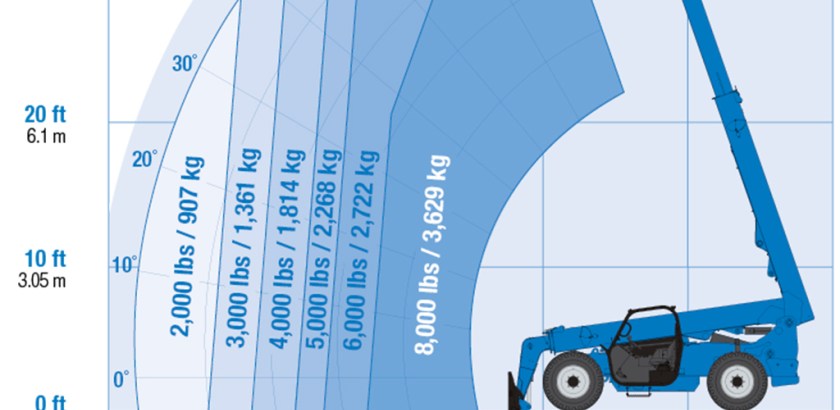
Understand the telehandler’s load chart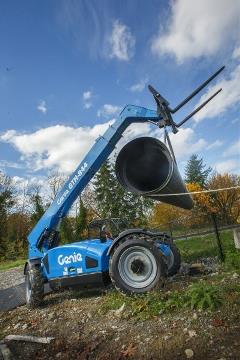 Like many aerial devices, telehandlers are rated for their load capacity, height and outreach. A peek at a telehandler’s load chart will tell an operator a lot about how much the machine can do, such as how much it can lift, how high it can lift the load and at what angle.
It is important when checking out a telehandler’s load chart to look at weight lifting capacity, but operators also need to look at where the telehandler can lift that weight. And, don’t forget that the telehandler attachment (e.g. fork, bucket, carriage or work platform) will also impact the telehandler’s load capacity, load height and reach. Be sure to look at the telehandler’s load chart that corresponds with the attachment being used before starting work.
Tips for applying the telehandler’s load chart
For safe use and productive operation, it is important that operators understand the telehandler’s load chart and how to apply that information to the jobsite’s needs. Here is some information for accurately calculating a telehandler’s lift capacity and applying what is outlined in the unit’s load charts:
- Always center the load on the forks and position the load so that it is completely against the back of the fork frame.
- Fork length should always be at least two-thirds the load length.
- All Genie® telehandler fork carriage load charts are based on a horizontal load center that is 24 in (61 cm) from the front vertical surface of the fork arm. For loads with a load center exceeding this value, operators need to determine the reduced load capacity for a specific load zone.
- Note that this does not account for a load center that is not centered between the forks or a vertical load center exceeding 24 in (61 cm) from the top face of the fork tine. Keep the load centered on the fork carriage.
- To calculate the reduced load capacity at a load center greater than the standard 24 in (61 cm) load center, multiply the zone capacity from the load chart by the appropriate reduction factor listed in the table below:
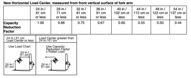
- Once the multiplier has been determined, complete the reduced load capacity calculations using this formula:

- Once the calculations are done, chart the information on the telehandler’s load chart to understand the unit’s load capacity, lift height and outreach available for each project.
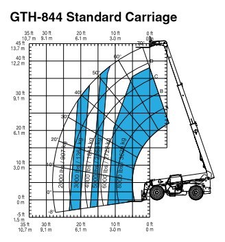
More information about each telehandler model’s unique load capacity, lift height and outreach can be found in the unit’s owner’s manual. Genie recommends that operators follow all the guidelines outlined in the telehandler’s owner’s manual for safe use and productive operation on every jobsite.
Your local Genie dealer can help you find the telehandler that’s right for you. Use our Dealer Locator to find your local Genie Telehandler dealer.
Related Posts

Genie Safety Minute: Machine Bulletin Lookup
Genie safety minute is intended to facilitate health and safety discussions on the job.
Continue Reading
National Safety Stand-Down: Rental Ready
Kicking the tires and lighting the fires isn’t enough
Continue Reading

Genie Safety Minute: Global Standards Requirements for MEWPs
Genie Safety Minute is intended to facilitate health and safety discussions on the job site.
Continue Reading


